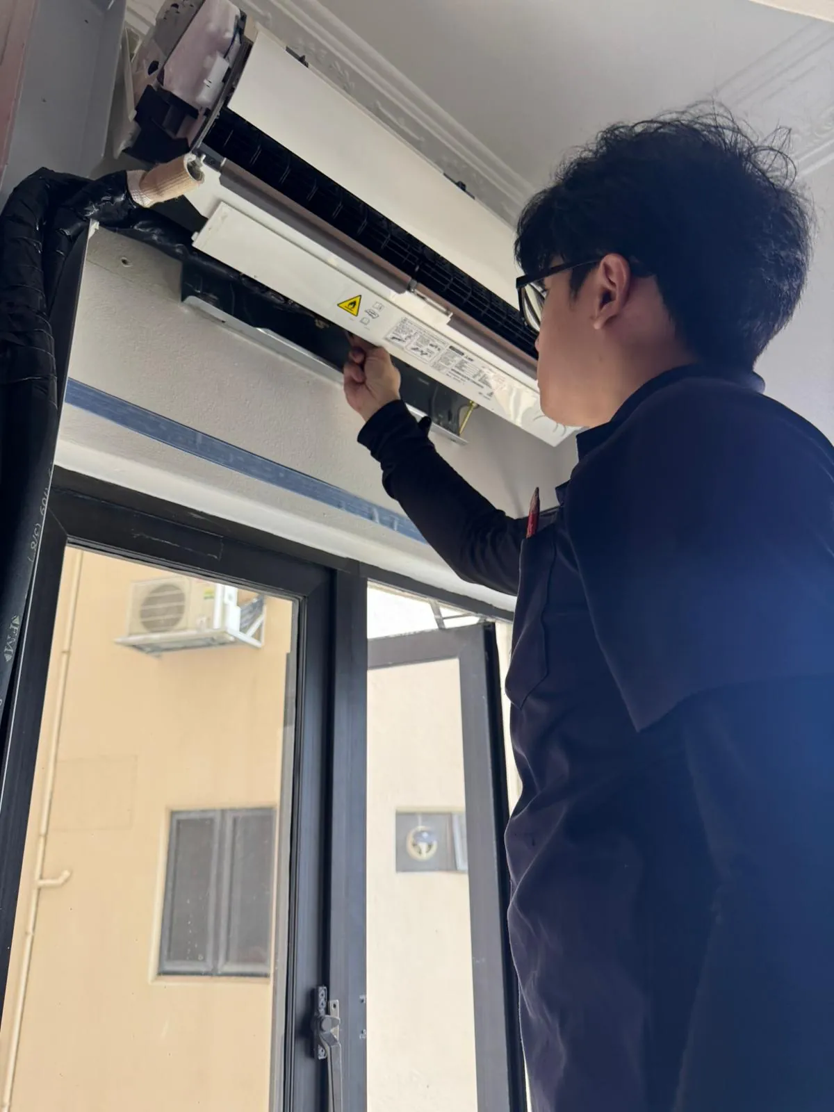
Ducted communication wiring repair in Singapore
On a ducted system, a fault that points to the communication wiring is not always the communication wiring. We confirm which unit shows the fault, test the surrounding mechanical and control paths, and quote the component only when it is proven responsible.
BCA-registered10,000+ jobs completed
Signs to check the ducted communication wiring path
These symptoms justify diagnosis, but they do not identify the replacement part by themselves.
Units lose contact or stop together
An open data path, missing unit power, address issue or failed transmit/receive stage can interrupt the network.Communication returns intermittently
Loose terminals, moisture, heat damage, screening, electrical noise or an unstable board can make the fault load-dependent.A serial or transmission code appears
The exact endpoints and the unit showing the code must be identified before the cable or either PCB is blamed.
Where the communication wiring fits in a ducted system
The component location and effect change with the system layout and the unit that shows the fault.
Residential concealed-ducted fan coils
The communication wiring fault differs by model; confirm the equipment labels before using the listed codes.Commercial ducted indoor units with wired controllers
The communication wiring fault differs by model; confirm the equipment labels before using the listed codes.Ducted units connected to multi-split, packaged or VRF outdoor systems
The communication wiring fault differs by model; confirm the equipment labels before using the listed codes.
Confirm your system
A communication code identifies a failed path, not an automatic interconnect-cable replacement. One concealed indoor unit can serve several rooms, so a single fan, sensor or drainage fault may affect an entire zone rather than one grille.
What can look like a failed communication wiring
The surrounding load, wiring, controls and operating condition are checked first.
Missing power at one endpoint
A healthy cable cannot exchange data with an indoor, outdoor, controller or branch device that has lost supply.Address or configuration fault
Wrong unit numbers, duplicate addresses or incompatible topology can interrupt otherwise healthy communication hardware.PCB transmit or receive failure
A failed board stage can make good wiring appear open or corrupt the data on the network.
Official ducted communication wiring fault evidence
119 model-scoped guides across 12 supported brands show where this component path appears in official diagnostics.
Carrier13 guides
- 06Communication failure between indoor and outdoor units
- 07Communication failure between indoor unit and wired controller
- 26 / 26-0 / 26-1 / 26-2Indoor-unit communication failure: connected indoor units cannot be found for 200 communication cycles
- 45Communication failure between outdoor units
- 46 / 46-0 / 46-1 / 46-4 / 46-5Communication failure with INV1 module board
- 47Communication failure with the wireless module
- 116 / 116-1 / 116-2 / 116-4 / 116-5Communication error between the module and control board
- E1Communication error between the indoor and outdoor unit
- E9Communication error between the indoor unit and wired controller
- EHbA / EHBACommunication error between indoor unit and external fan module
- EL01IDU and ODU communication error
- EL11Communication malfunction between the main and secondary units
- View all Carrier error-code guides
Daikin11 guides
- C1Failure of transmission between indoor PCB and sub PCB
- LCTransmission fault between control PCB and inverter PCB
- M8Transmission fault between optional centralized-control controllers
- U3Check operation not executed or transmission error
- U4Transmission fault between indoor and outdoor unit
- U5Transmission fault between indoor unit and remote controller
- U8Transmission fault between remote controllers
- U9 / U9-01Transmission fault in another system
- UETransmission fault between indoor unit and centralized control equipment
- UJTransmission fault with accessory device
- UJ-35VAM abnormality or VAM-to-EKVDX system error
Fujitsu7 guides
- 3AIndoor unit communication circuit (wired remote controller) error
- 11Serial communication error between indoor/outdoor units
- 12Remote controller communication error
- 13Communication error between Outdoor unit
- 14Network communication error
- 16Peripheral device communication error
- 18External communication error
Gree12 guides
- 43 / 44 / 45 / 46Communication failure with Unit A
- 55 / 56 / 57 / 58Unit A communication wire misconnection or expansion valve malfunction
- C0Communication malfunction between IDU, ODU and IDU’s wired controller
- C1Communication malfunction between main control and DC-DC controller
- C2Communication malfunction between main control and inverter compressor driver
- C3Communication malfunction between main control and inverter fan driver
- CUCommunication malfunction between indoor unit and receiving lamp plate
- ddWrong communication wire connection or electronic expansion valve detection status
- dnWrong communication wire connection or electronic expansion valve malfunction
- E6Communication malfunction
- P6Communication malfunction between main control and drive
- UFCommunication malfunction between indoor unit and inspection board
Hitachi5 guides
LG11 guides
- 204C / 204C + HR unit numberheat-recovery unit: Communication error between the outdoor unit and heat-recovery unit
- 205C / 205C + HR unit numberheat-recovery unit: Communication error between a 2A-series heat-recovery unit and its 485 modem
- 242*central controller: Central-controller network communication error
- CH03indoor unit: Communication error between the zone controller and indoor unit
- CH05 / CH53 / E0indoor unit: Communication error between the outdoor-unit PCB and indoor-unit PCB
- CH52master outdoor unit: Communication error between the outdoor main PCB and inverter PCB
- CH104 / 104 / 1041 / 1042 / 1043master outdoor unit: Communication error between master and slave outdoor units
- CH105 / 105 / 1051 / 1052 / 1053master outdoor unit: Communication error between the fan PCB and inverter-compressor PCB
- CH145 / 145 / 1451 / 1452 / 1453master outdoor unit: Communication error between the outdoor main board and external board
- CH182 / 182 / 1821 / 1822 / 1823master outdoor unit: Communication error between external-board main and sub MICOMs
- CH237 / CH238 / CH237 / CH238indoor unit: Indoor-side loss of communication from the outdoor-unit PCB
Midea13 guides
- C21Indoor/outdoor communication fault
- C41Indoor main-PCB to fan-driver PCB communication fault
- C51Indoor unit to wired-controller communication fault
- C52Indoor unit to wireless-kit communication fault
- C61Indoor main-PCB to display-board communication fault
- C71Secondary-to-primary AHU-kit communication fault
- C73Linked humidification indoor unit to primary indoor unit communication fault
- C74Linked FAPU to primary indoor unit communication fault (serial setting)
- C75Linked FAPU to primary indoor unit communication fault (non-serial setting)
- C76Primary-to-secondary wired-controller communication fault
- C77Indoor main PCB to expansion board No. 1 communication fault
- C78Indoor main PCB to expansion board No. 2 communication fault
- View all Midea error-code guides
Mitsubishi Electric17 guides
- 6602M-NET transmission-processor hardware error
- 6603M-NET transmission bus busy
- 6606Communication error with the M-NET transmission processor
- 6607M-NET no-acknowledgement communication error
- 6608M-NET no-response communication error
- 6801PZ-43SMF-E remote-controller communication error
- 6831PZ-62DR remote-controller no-reception communication error
- 6832PZ-62DR remote-controller synchronization-recovery communication error
- 6833PZ-62DR remote-controller communication hardware error
- 6834PZ-62DR start-bit detection or leader-follower communication error
- E0Remote controller transmission error
- E4Communication error between wired remote controller and indoor unit
- View all Mitsubishi Electric error-code guides
Mitsubishi Heavy Industries5 guides
Panasonic4 guides
Samsung9 guides
- E101 / E102 / E101 / E102Indoor unit communication error. Indoor unit cannot receive any data from the outdoor unit.
- E201Communication error between indoor and outdoor units (installation number setting error, repeated indoor unit address, or indoor unit communication cable error)
- E202Communication error between indoor and outdoor units (communication error on all indoor units or outdoor unit communication cable error)
- E203Communication error between main and sub outdoor units
- E205Communication error on all PBA within the outdoor unit C-Box, or communication cable error
- E206E206-C001: HUB PBA communication error / E206-C002: FAN PBA communication error / E206-C003: INV1 PBA communication error / E206-C004: INV2 PBA communication error
- E460Indoor/outdoor communication wire connected to a power terminal
- E601Communication error between the indoor unit and wired controller
- E602Communication error between master and slave wired controllers
Toshiba12 guides
- C05Central controller transmission fault
- E03Indoor unit lost communication from the remote controller or network adaptor
- E04Indoor/outdoor serial communication error
- E06An indoor unit dropped out of normal communication
- E10Indoor main-controller to motor-microcontroller communication fault
- E11Application control kit to indoor PCB communication fault
- E17Communication trouble between indoor units and the flow-selector unit
- E18Indoor header and follower units lost periodic communication
- E26A follower outdoor unit dropped out of communication
- E31Communication fault between inverter-box PCBs
- J01Communication trouble between indoor units and the flow-selector unit
- J02Communication trouble between control boards in a multi-port flow-selector unit
Brand codes are not interchangeable. Open the matching brand and model family before using a fault guide.
How we diagnose ducted communication wiring faults
The component is tested as part of its complete controlled path.
Map the exact communication path
The unit showing the code, endpoints, terminals, addresses and any branch or central controllers are recorded.
Verify power and physical wiring
Supply, terminal order, continuity, insulation condition, polarity and visible damage are checked safely.
Separate cable and board stages
Communication indicators and measured behaviour determine whether wiring, configuration or electronics failed.
The communication wiring repair decision
The result may be cleaning, wiring, control, another component or the named part.
Repair terminals or cable
This fits when the data path is open, crossed, damaged, wet or poorly terminated.Correct addresses or configuration
A topology or setup problem should be resolved without replacing healthy hardware.Repair the failed interface or PCB
Electronics replacement follows only after unit power and the physical network are proven.
We identify the failed stage, exact model, part assembly and lead time before you approve work.
Useful repair references
Use the matching system, brand or component page to narrow the next step before booking.
Related repair paths
Workmanship warranty
We stand behind the repair we carry out, and we are straight about the part of the cover we do not set ourselves.
Labour
30-day workmanship warranty. If the same fault returns from our repair, we come back and the labour is on us, with no second diagnostic visit fee.
Parts
Parts carry the distributor's warranty for that component, so the term varies by part. We tell you both terms before you approve the work.
Frequently asked questions about Ducted communication wiring repair in Singapore
Does a ducted communication wiring code prove the part failed?
Which brands support this communication wiring diagnostic scope?
Can this communication wiring fault affect more than one zone?
What should I send before booking?
We cover all of Singapore. Find aircon services in your area.
Describe your situation
Tell us what’s going on. Symptoms, setup, photos, anything we should know. We’ll assess and come back with the right next step.